
Electronic circuit board HighQuality Technology Stock Photos Creative Market
Chapter 1 Resistors Chapter 2 Capacitors Chapter 3 LEDs Chapter 4 Transistors Chapter 5 Inductors Chapter 6 Diodes Chapter 7 Integrated Circuits Chapter 8 Transformers Chapter 9 Sensors Chapter 10 Potentiometers Chapter 11 Crystal Oscillators Chapter 12 Switches and Relays Chapter 13 Silicon-Controlled Rectifier (SCR) Chapter 14

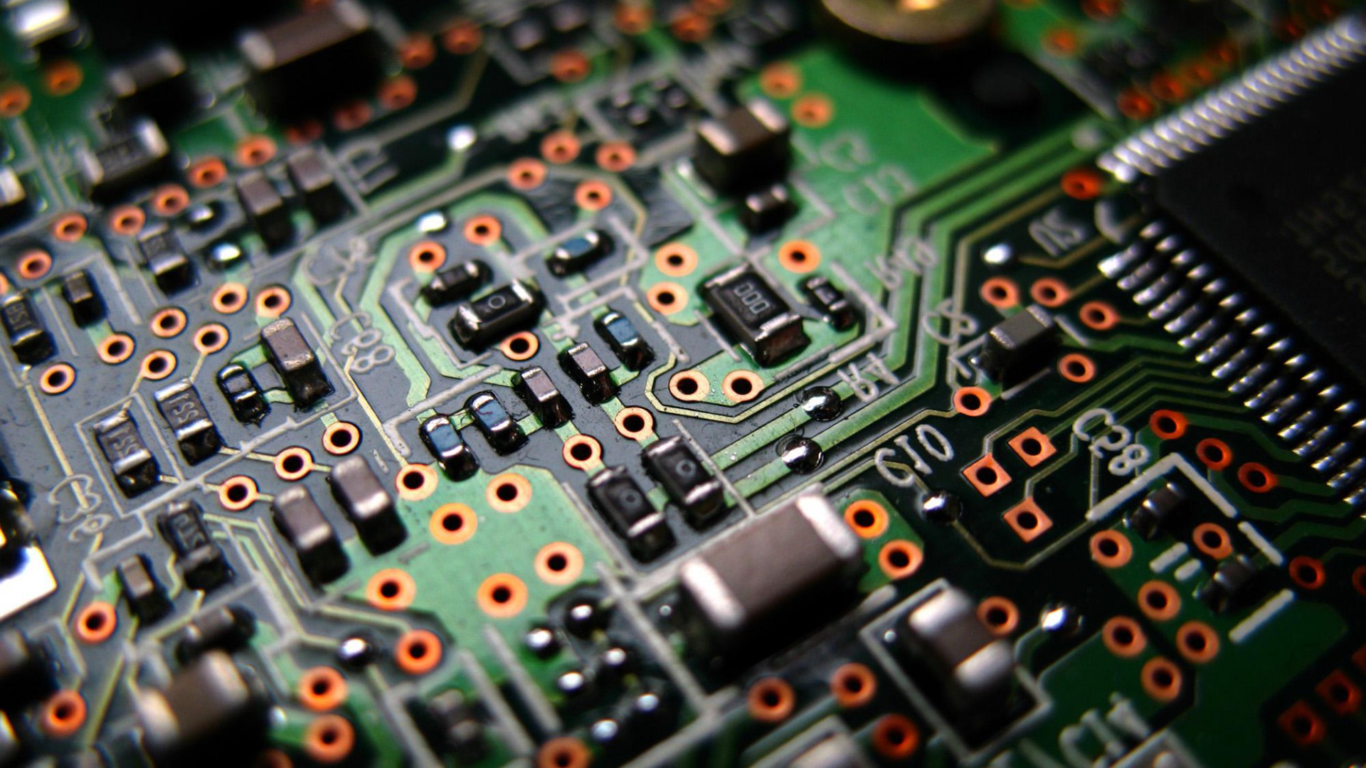
Electronic circuit board close up. HighQuality Technology Stock Photos Creative Market
Solder-less circuit boards are great resources for prototyping and simple circuits but they have their limitations. These limitations include the following:. Unlike a breadboard, you will need to practice on your soldering technique as electrical components must be soldered onto them. With a 0.1 inch hole, you will also require components.

[GUiDE] The Basic Set Up Of A PCB Circuit Board (2018)
Abstract: More and more printed circuit boards (PCBs) will be used in electric aircraft to achieve higher power density of the on-board electric system, while PCBs in aircraft are more likely to generate partial discharges (PDs) due to external factors such as compact structure and low air pressure. Therefore, this paper proposes a fluorescent fiber-based method for detecting and evaluating.

How to Make a Circuit Board to Demonstrate Simple Electrical Circuits for Kids Electricity
An electronic circuit is composed of individual electronic components, such as resistors, transistors, capacitors, inductors and diodes, connected by conductive wires or traces through which electric current can flow. It is a type of electrical circuit.
Electric Board
Circuit Construction Kit: DC - PhET Interactive Simulations

Electrical Distribution Board Wiring Diagram
A printed circuit board is a bunch of electronic components interconnected via conductive paths printed on a baseboard. The electronic components and conductive paths are based on a map, the schematic diagram. This diagram is drawn based on widely-accepted rules and symbols. The symbols used in schematic diagrams are according to standards that.
HD Circuit Board Background
A printed circuit board is a rigid structure that contains electrical circuitry made up of embedded metal surfaces called traces and larger areas of metal called planes. Components are soldered to the board onto metal pads, which are connected to the board circuitry. This allows components to be interconnected.
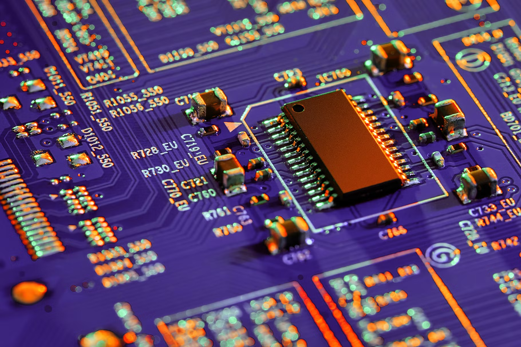
Electronic circuit board close up. Background Stock Photos Creative Market
What is a PCB? A printed circuit board (PCB) is an electronic assembly that uses copper conductors to create electrical connections between components. Printed circuit boards provide mechanical support for electronic components so that a device can be mounted in an enclosure.

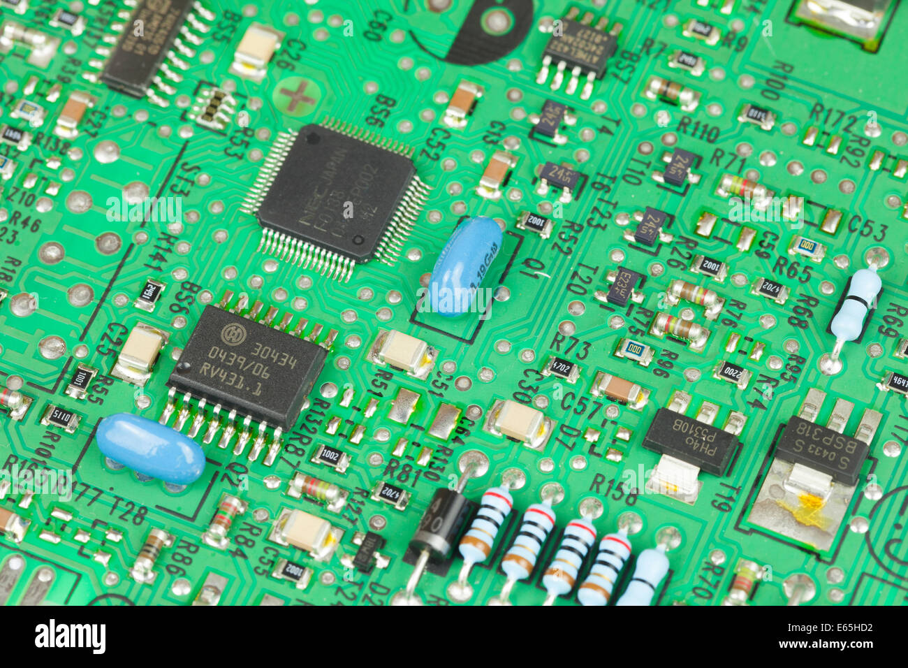
an electronic circuit board with parts labeled
Identifying the electronic components on a circuit board is important during the designing, assembling, deployment, and troubleshooting stages of the PCB production process. A reference designator is a set of alphanumeric codes used to identify a specific component on the PCB board. The signs + and - are usually marked on the circuit board to.
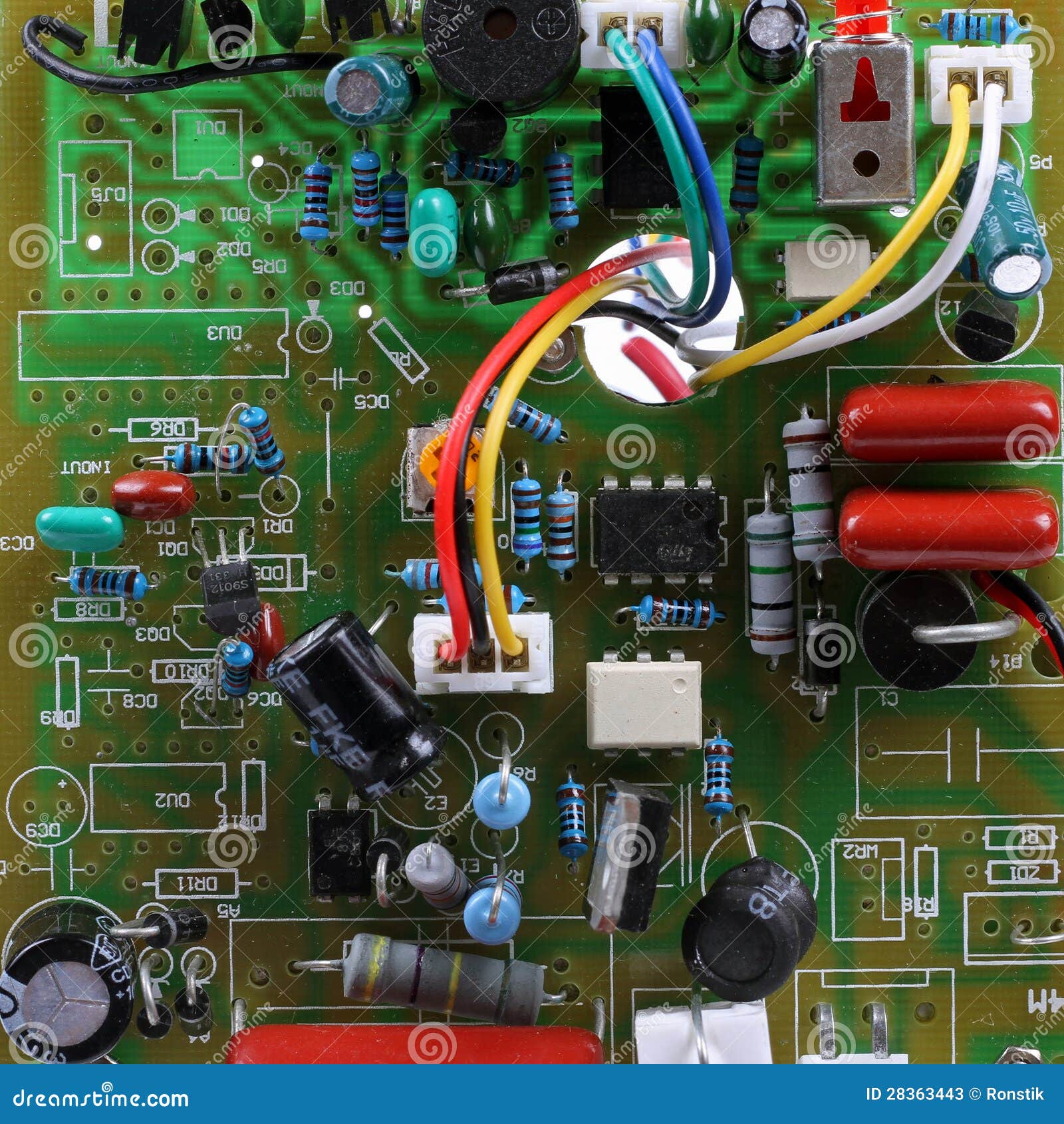
Circuit Board With Electrical Components Stock Photos Image 28363443
What are Circuit Boards? A circuit board, also known as a printed circuit board (PCB), is a fundamental component in electronics. It's the backbone of most electronic devices, providing a platform for the arrangement and interconnection of electronic components.

How To Do An Electrical Circuit Boards Work Wiring Diagram
Acquire a circuit board. Circuit boards are about a dollar apiece, and are simply a layer of copper over an insulator. The typical size is usually 3.5 inches (8.9 cm) by 5 inches (12.7 cm). Drawing is simple; all that is required is an indelible marker, such as a Sharpie.

Electric circuit board stock image. Image of circuit 225237181
Step 1: Schematic Capture Step 2: Create a Blank PCB Layout Step 3: Synchronize Schematics to Your PCB Board Design Step 4: Designing Your PCB Stackup Expand Table of Contents Circuit board design and layout is both an art and a science, and it can be difficult to get started designing a new circuit board from scratch.

How to Make a Circuit Board to Demonstrate Simple Electrical Circuits for Kids Engineering
Check the Power Module. If the components look fine, you'll need to power up the circuit board. Measure the voltage of the power rails with the multimeter. Both the input and output of the voltage regulator need to show the expected values. Check the fuse if the input voltage measured at the voltage regulator is 0V.
Electric Circuit board Stock Photo by ©jeka2009 141825260
PCB is an acronym for printed circuit board. It is a board that has lines and pads that connect various points together. In the picture above, there are traces that electrically connect the various connectors and components to each other. A PCB allows signals and power to be routed between physical devices.
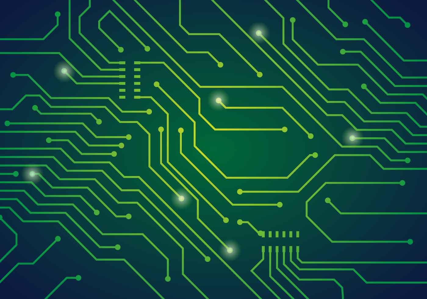
Circuit Board Vector Art, Icons, and Graphics for Free Download
The electric circuits are closed-loop or paths, forming a network of electrical components where electrons can flow. This path is made using electrical wires and is powered by a source, like a battery.
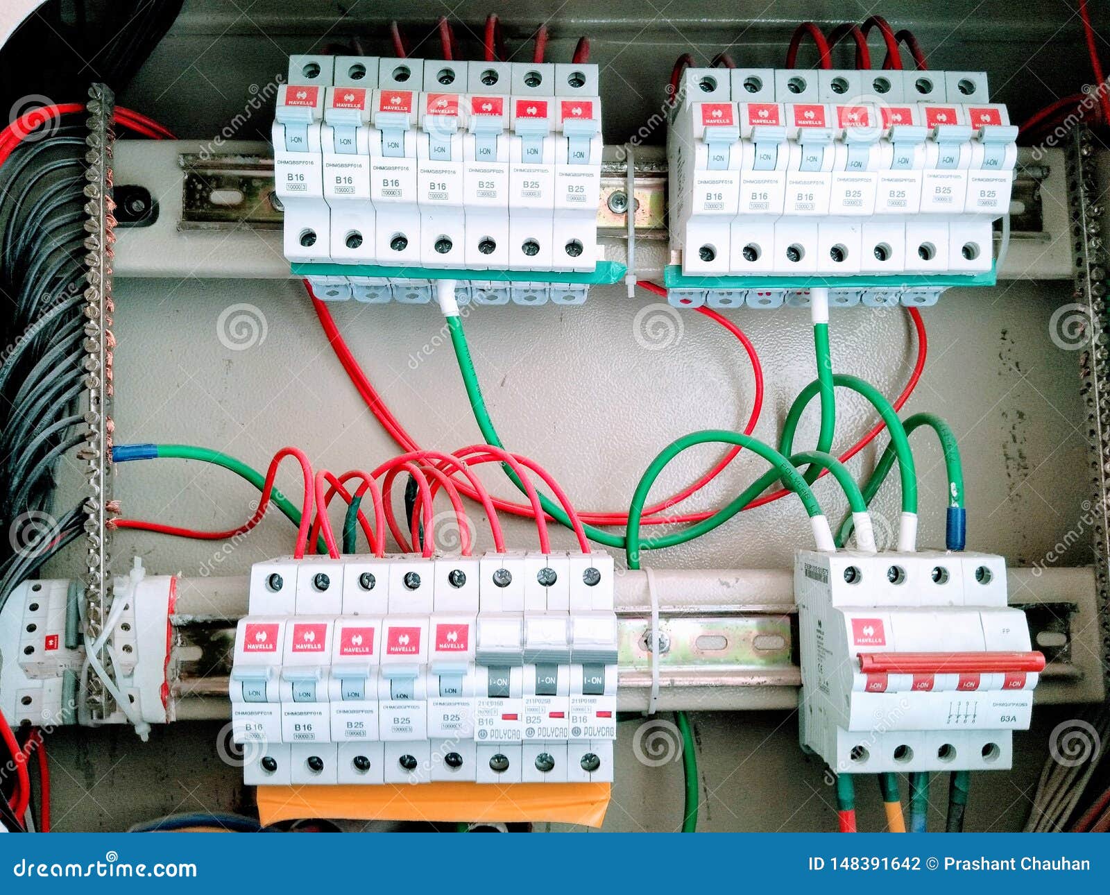
A Picture of Electric Circuit Board Stock Photo Image of electrical, electricity 148391642
A printed circuit board ( PCB ), also called printed wiring board ( PWB ), is a medium used to connect or "wire" components to one another in a circuit.